Manual transmission shift linkage connects the gear shifter to the transmission, enabling precise gear selection. It includes components like shift forks, synchronizers, and bushings, ensuring smooth transitions. Diagrams are essential for understanding and adjusting the system, which is critical for optimal performance and preventing mechanical issues.
1.1 Overview of Manual Transmission
A manual transmission is a type of gearbox that allows drivers to manually select gears using a clutch pedal and shift lever. It relies on mechanical components, such as gears, shafts, and synchronizers, to transfer power from the engine to the wheels. The driver controls gear changes, providing better fuel efficiency and performance compared to automatic transmissions. The system includes a shift linkage that connects the gear shifter to the transmission, enabling precise gear selection. This linkage ensures smooth transitions between gears by engaging and disengaging components like synchronizers and shift forks. Diagrams of the manual transmission system are essential for understanding how these parts interact and function together. They provide a visual guide for technicians and enthusiasts to diagnose issues, perform maintenance, and make adjustments. The manual transmission remains a popular choice for its simplicity, reliability, and driver engagement.
1.2 Importance of Shift Linkage
The shift linkage plays a crucial role in manual transmissions by connecting the gear shifter to the transmission, enabling precise gear selection. Properly functioning shift linkage ensures smooth and accurate gear changes, directly impacting vehicle performance and control. If the linkage is worn or misaligned, it can lead to issues like difficulty shifting gears or gears that slip out, potentially causing damage to transmission components. Regular maintenance and adjustment of the shift linkage are essential to maintain optimal performance. Diagrams are invaluable for understanding the system’s layout and troubleshooting problems. They provide a clear visual guide for identifying wear points, such as bushings and bearings, and ensuring correct adjustments. Properly maintained shift linkage contributes to a more responsive and reliable driving experience, making it a critical component of any manual transmission system.

Components of the Shift Linkage System
The shift linkage system includes the shift lever, shift forks, synchronizers, and bushings. These components work together to transfer the driver’s gear selection to the transmission, enabling smooth gear changes.
2.1 Shift Lever
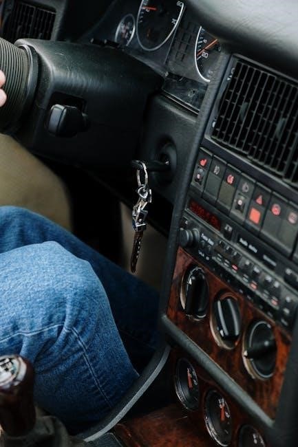
The shift lever is a critical component of the manual transmission system, acting as the driver’s interface for selecting gears. It is typically located on the center console or directly connected to the transmission. The lever is linked to the shift linkage system, converting the driver’s manual input into precise gear selections. In most setups, the shift lever is connected via a rod or cable to the transmission’s internal mechanisms. Proper alignment and adjustment of the shift lever ensure smooth, accurate gear changes. Diagrams often highlight the shift lever’s connection points, such as the shift fork and synchronizers, illustrating how it engages gears within the transmission. Maintenance, like tightening or replacing worn bushings, is essential to prevent loose or misaligned shifts. Understanding the shift lever’s role is fundamental for diagnosing issues and ensuring optimal performance.
2.2 Shift Forks
Shift forks are integral to the manual transmission system, playing a pivotal role in engaging and disengaging gears. These forks are operated by the shift linkage, moving along the transmission’s shaft to align gears. Diagrams often depict the shift forks’ interaction with synchronizers, showcasing how they slide over gear teeth to facilitate smooth shifts. The forks are typically connected to the shift rail, which is controlled by the shift lever. Proper alignment and lubrication of the forks are crucial to prevent grinding or difficulty in shifting. Worn or damaged forks can lead to transmission issues, emphasizing the importance of regular maintenance. Understanding their function through diagrams aids in diagnosing problems and performing repairs effectively.
2.3 Synchronizers
Synchronizers are essential components in a manual transmission system, responsible for smoothly engaging and disengaging gears. They work by equalizing the speed of the gear and the shaft before locking them together, which prevents grinding and ensures seamless transitions. Diagrams often illustrate how synchronizers are connected to the shift forks and gears, showcasing their role in the linkage system. Each synchronizer typically serves a specific gear set, and their operation is synchronized with the movement of the shift lever. Proper lubrication and alignment are critical for their functionality. Worn or damaged synchronizers can lead to difficulty in shifting gears, often requiring replacement. Understanding their operation through diagrams helps in diagnosing issues and performing effective repairs, ensuring optimal transmission performance.
2.4 Bushings and Bearings
Bushings and bearings are critical for reducing friction and wear within the shift linkage system. They are placed at key connection points, such as between the shift lever and the transmission, to ensure smooth operation. Over time, these components can wear out, leading to loose or binding shifts. Replacing worn bushings and bearings is essential to maintain precise gear engagement. Diagrams often highlight their locations and connections, aiding in identification during repairs. Proper lubrication and alignment are vital for their longevity. If neglected, worn bushings can cause misalignment in the linkage, leading to further damage. Regular inspection and maintenance are recommended to prevent such issues, ensuring the system operates efficiently and reliably. Understanding their role through diagrams helps in diagnosing wear and performing effective replacements, which are crucial for maintaining smooth shifting performance.
Types of Shift Linkage Systems
Manual transmissions use rod-based or cable-based shift linkage systems. Rod-based systems rely on mechanical connections, while cable-based systems use flexible cables for gear selection, offering smoother operation and easier adjustment.
3.1 Rod-Based Systems
Rod-based shift linkage systems are mechanical setups where solid rods connect the gear shifter to the transmission. These rods are typically secured with couplers and bushings, ensuring precise alignment and minimal play. The system relies on a direct physical connection, providing tactile feedback and durability. Rods are preferred in high-performance applications due to their strength and resistance to wear. However, they can be heavier and require more space compared to cable-based systems. Proper adjustment of rod-based linkages is crucial to maintain smooth shifting and prevent mechanical binding. Over time, bushings may wear, leading to sloppiness in gear changes, necessitating periodic maintenance or replacement to uphold performance and reliability.
3.2 Cable-Based Systems
Cable-based shift linkage systems utilize a flexible cable connected to the gear shifter and transmission. This design offers weight reduction, easier installation, and adaptability to various vehicle layouts. The cable operates within a protective sheath, minimizing friction and ensuring smooth gear engagement. Cable systems are commonly found in modern vehicles due to their compactness and ease of adjustment. However, they can be prone to wear, such as fraying or stretching, which may lead to imprecise shifting. Regular inspection and replacement of worn cables are essential to maintain optimal performance. Despite these maintenance needs, cable-based systems remain popular for their simplicity and effectiveness in providing reliable gear transitions in both front-wheel and rear-wheel drive configurations.

Adjustment and Maintenance
Regular maintenance ensures smooth shifting by adjusting linkage components and replacing worn bushings. Diagrams guide precise adjustments, preventing issues like misalignment or gear engagement problems.
4.1 Steps to Adjust Shift Linkage
Adjusting the shift linkage involves loosening the locking pin and aligning the rods properly. Ensure the gear shifter is in neutral, then tighten the pin to maintain alignment. Referencing a diagram helps in identifying correct positions and connections, ensuring smooth gear transitions.
4.2 Replacing Worn Bushings
Replacing worn bushings in the shift linkage is crucial for maintaining smooth gear transitions. Start by accessing the linkage system, often requiring the removal of the transmission or shifter assembly. Use a diagram to locate the bushings, typically found at pivot points and rod connections. Remove the old bushings carefully, ensuring not to damage surrounding components. Install new bushings by aligning them properly and securing them with the provided hardware. Tighten all connections firmly but avoid over-tightening, which can restrict movement. Finally, test the system to ensure smooth operation and precise shifting. Regular replacement of worn bushings prevents further damage and maintains optimal performance of the manual transmission system.
Common Issues and Troubleshooting
Common issues with manual transmission shift linkage include difficulty shifting gears and grinding noises, often caused by worn bushings or misaligned components. Proper diagnosis and timely repairs are essential.
5.1 Symptoms of Faulty Linkage
Symptoms of a faulty manual transmission shift linkage include difficulty shifting gears, grinding noises, and inconsistent gear engagement. Drivers may experience delays in shifting or complete failure to engage gears, especially when shifting into higher gears. Another common symptom is looseness in the shifter, causing imprecise control. These issues often stem from worn bushings, misaligned components, or damaged shift forks. In some cases, metal-on-metal noises may indicate advanced wear. If left unaddressed, these problems can lead to transmission damage and costly repairs. Early identification of these symptoms is crucial for maintaining smooth operation. Consulting a shift linkage diagram can help pinpoint the source of the issue, ensuring accurate troubleshooting and repair.
5.2 How to Diagnose Problems
Diagnosing issues in a manual transmission shift linkage involves a systematic approach. Start by observing symptoms like grinding noises or difficult shifting. Inspect the shift linkage for visible wear, such as loose connections or damaged components. Use a shift linkage diagram to identify and locate parts like bushings, shift forks, and synchronizers. Test the shifter’s movement to check for play or binding. If gears are hard to engage, it may indicate worn synchronizers or misaligned forks. Additionally, listen for unusual noises during shifting, which can signal damaged or misaligned parts. By cross-referencing symptoms with the diagram, you can pinpoint the root cause. Tools like a torque wrench and inspection mirror can aid in evaluating the system. Early diagnosis prevents further damage and ensures precise repairs.
Diagrams and Schematics
Diagrams and schematics provide visual representations of manual transmission shift linkage systems, detailing components like shift rails, forks, and synchronizers. They aid in understanding system layout and connections.
6.1 Reading the Diagram
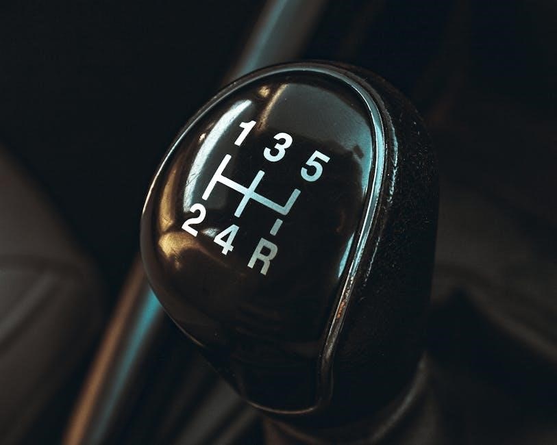
Reading a manual transmission shift linkage diagram requires identifying key components and understanding their interconnections. Start by locating the shift lever, which is typically at the top of the diagram. Trace the linkage to the shift forks, synchronizers, and gear selector rails. Pay attention to labels and color coding, which often differentiate between neutral, reverse, and forward gears. Note how the shift rail moves the fork to engage specific gears. Look for arrows indicating the direction of movement when shifting. Identify bushings and bearings, as these are common wear points. Familiarize yourself with the layout to understand how the shifter’s motion translates to gear engagement. This visual guide helps diagnose issues, such as misaligned forks or worn bushings, by comparing the diagram to your actual setup. Practice tracing the linkage path to grasp how each part interacts during gear changes.
6.2 How Diagrams Aid in Repairs
Diagrams of manual transmission shift linkages are invaluable during repairs, providing a clear visual guide to component locations and connections. They help identify worn or damaged parts, such as bushings or shift forks, by comparing the diagram to the actual setup. By tracing the linkage path, technicians can diagnose issues like misalignment or improper engagement. Diagrams also guide the reinstallation of components, ensuring rods, cables, and forks are correctly positioned. This visual reference minimizes errors during disassembly and reassembly, especially for complex systems. Additionally, diagrams aid in troubleshooting symptoms like difficulty shifting or gear slippage by highlighting potential problem areas. They serve as a roadmap, streamlining the repair process and reducing guesswork, making them an essential tool for both professionals and DIY enthusiasts working on manual transmissions.
Application in Specific Transmissions
Manual transmission shift linkage diagrams are essential for specific transmissions like the TH350 and Muncie 4-Speed. They provide detailed views of components and connections, aiding in precise repairs and adjustments, ensuring smooth gear engagement and optimal performance.
7.1 TH350 Shift Linkage
The TH350, a popular automatic transmission, utilizes a specific shift linkage system. Its design ensures smooth gear transitions through a series of mechanical connections. Diagrams for the TH350 illustrate how the shift linkage interacts with the transmission’s internal components, such as the valve body and gear sets. These visual guides are crucial for technicians to understand the flow of hydraulic pressure and mechanical actuation. By referring to these diagrams, one can identify potential issues like worn or misaligned components, which may cause slipping or hesitation between gears. Regular inspection and adjustment of the shift linkage, as detailed in the diagrams, can prevent major repairs and maintain optimal performance. The TH350’s shift linkage is a testament to the precision engineering required in automatic transmissions, ensuring reliable operation for decades.
7.2 Muncie 4-Speed
The Muncie 4-speed manual transmission is a highly regarded choice among classic car enthusiasts, particularly for its durability and performance. Its shift linkage system plays a pivotal role in facilitating smooth gear transitions. The Muncie’s design incorporates shift forks, synchronizers, and a robust linkage mechanism to ensure precise engagement of each gear. Diagrams of the Muncie 4-speed are invaluable for technicians, as they provide a clear visual representation of how the shift linkage interacts with the transmission’s internal components. These diagrams highlight the importance of proper adjustment and maintenance to avoid issues like misalignment or wear on critical parts. By referencing these diagrams, enthusiasts can troubleshoot common problems, such as difficulty shifting into specific gears, and perform necessary adjustments to restore optimal functionality. The Muncie’s shift linkage is a testament to the engineering of classic manual transmissions, offering a blend of simplicity and effectiveness that appeals to both restorers and drivers seeking precise control over their vehicle’s performance.